Water and Nutrient Management
Perhaps the most important components for economic success in the produce industry is addressing water and nutrient management. By incorporating current technologies and Best Management Practices (BMPs), producers water and nutrients can be managed to maintain high yields, reduce costs, and protect natural resources.
Topics in this category offer scientifically-sound application methods such as drip irrigation, soil moisture sensors, and others:
On-Farm Blue Dye Demonstrations
Improving irrigation management in vegetable crop production reduces production costs, saves water, and reduces the risk of nutrient leaching. As water movement in the root zone below mulched beds is difficult to see, injecting soluble dye through the drip irrigation system provides a simple and practical method to visualize water movement in the soil.
These three modules provide insight into the blue dye injection process:
-
Introduction
-
Presenters
- Bob Hochmuth is a multi-county Extension agent at the NFREC - Suwannee Valley working in the areas of small farms, commercial vegetables, and protected culture. His specialties include alternative crops, hydroponics, plastic mulch, and drip irrigation technology. Bob was raised on a commercial vegetable farm and has been an Extension agent since 1982.
- Dr. Eric Simonne is an Extension Specialist in the Horticultural Sciences Department with responsibilities in water and nutrient management for vegetables.
Publications
-
-
Application Methods
-
Presenters
- Bob Hochmuth is a multi-county Extension agent at the NFREC - Suwannee Valley working in the areas of small farms, commercial vegetables, and protected culture. His specialties include alternative crops, hydroponics, plastic mulch, and drip irrigation technology. Bob was raised on a commercial vegetable farm and has been an Extension agent since 1982.
- Dr. Eric Simonne is an Extension Specialist in the Horticultural Sciences Department with responsibilities in water and nutrient management for vegetables.
Publications
-
-
Results and Impacts
-
Presenters
- Bob Hochmuth is a multi-county Extension agent at the NFREC - Suwannee Valley working in the areas of small farms, commercial vegetables, and protected culture. His specialties include alternative crops, hydroponics, plastic mulch, and drip irrigation technology. Bob was raised on a commercial vegetable farm and has been an Extension agent since 1982.
- Dr. Eric Simonne is an Extension Specialist in the Horticultural Sciences Department with responsibilities in water and nutrient management for vegetables.
Publications
-
Small Farms Drip-Irrigation
Drip Irrigation offers farmers an economical and efficient method to water their crops, with small farm operations adopting drip irrigation practices on a smaller scale.
These modules provide information on setting up drip irrigation, best management practices and testimonials from small acreage and organic producers:
-
Introduction and Equipment
-
Presenters
- Bob Hochmuth is a multi-county Extension agent at the NFREC - Suwannee Valley working in the areas of small farms, commercial vegetables, and protected culture. His specialties include alternative crops, hydroponics, plastic mulch, and drip irrigation technology. Bob was raised on a commercial vegetable farm and has been an Extension agent since 1982.
- Dr. Eric Simonne is an Extension Specialist in the Horticultural Sciences Department with responsibilities in water and nutrient management for vegetables.
Publications
-
-
Installation Methods in the Field
-
Presenters
- Bob Hochmuth is a multi-county Extension agent at the NFREC - Suwannee Valley working in the areas of small farms, commercial vegetables, and protected culture. His specialties include alternative crops, hydroponics, plastic mulch, and drip irrigation technology. Bob was raised on a commercial vegetable farm and has been an Extension agent since 1982.
- Dr. Eric Simonne is an Extension Specialist in the Horticultural Sciences Department with responsibilities in water and nutrient management for vegetables.
Publications
-
-
Franklin - Strawberry Production Demonstration
-
Presenters
- Jim Devalerio is the County Extension agent in Bradford County working with agriculture, horticulture and community development. Jim has active programs in educating small farmers on alternative crops and new technologies and has been instrumental in helping start a new community farmers market in Starke.
Bob Hochmuth is a multi-county Extension agent at the NFREC - Suwannee Valley working in the areas of small farms, commercial vegetables, and protected culture. His specialties include alternative crops, hydroponics, plastic mulch, and drip irrigation technology. Bob was raised on a commercial vegetable farm and has been an Extension agent since 1982.
Publications
- Jim Devalerio is the County Extension agent in Bradford County working with agriculture, horticulture and community development. Jim has active programs in educating small farmers on alternative crops and new technologies and has been instrumental in helping start a new community farmers market in Starke.
-
-
Cognito Farm - Vegetable Production Demonstration
-
Presenters
- Bob Hochmuth is a multi-county Extension agent at the NFREC - Suwannee Valley working in the areas of small farms, commercial vegetables, and protected culture. His specialties include alternative crops, hydroponics, plastic mulch, and drip irrigation technology. Bob was raised on a commercial vegetable farm and has been an Extension agent since 1982.
- Sandra (Sam) Williams and her husband Jerry, own and operate Cognito Farm. They use sustainable farming practices to raise grass-fed beef, pastured poultry and vegetables for local customers. Sam also helps manage the Bradford Farmers Market in Starke, FL.
Publications
-
Soil Moisture-Based Irrigation Systems
-
Introduction
-
Welcome and Outline of Contents
In this video we introduce the IFAS virtual field day on soil moisture-based irrigation. The use of this irrigation system is proposed as a viable method for conserving the water quality and quantity while maintaining agricultural yields or landscape quality. The outline of the virtual field day as well as the main components of an irrigation system are presented here.
Presenters
- Dr. Rafael Muñoz-Carpena specializes in surface, vadose, zone and groundwater hydrology; water quality modeling; water conservation in irrigation system design and operation.
Dr. Michael D. Dukes specializes in irrigation and drainage engineering; water quantity and quality issues; crop consumptive use; Best Management Practices to reduce nonpoint source pollution.
Publications
- Alternatives of Low Cost Soil Moisture Monitoring Devices for Vegetable Production in South Miami-Dade County
- Automatic Irrigation Based on Soil Moisture for Vegetable Crops
- Field Devices For Monitoring Soil Water Content
- Principles of On-Farm Water Management
- Dr. Rafael Muñoz-Carpena specializes in surface, vadose, zone and groundwater hydrology; water quality modeling; water conservation in irrigation system design and operation.
-
-
Principles: Soil Moisture-Based Irrigation Systems
-
Timed Irrigation
The timer-based irrigation system is a simple automatic irrigation system method that uses a standard timer or irrigation controller. A timer will control the start time and duration of the irrigation event.
Bypass Timer Irrigation
The bypass timer irrigation system is a simple and potentially efficient irrigation method. A soil moisture sensor is interfaced with the regular timer-based system through a controller unit.
On-Demand Irrigation
Potentially the most water efficient is the on-demand soil moisture-based irrigation system. It is a sensor based system that requires no timer. The irrigation both starts and stops depending on the soil moisture probe reading.
This system is not used in vegetable production, since it can potentially open all irrigation valves in a field at the same time and exceed the available water supply provided by the pump.
Publications
-
-
Components
-
Irrigation Components
A standard irrigation timer is presented in this video. This is an essential component used in conjunction with the soil moisture sensor to control the irrigation. The soil moisture sensor is used to automatically bypass scheduled irrigation events when the soil moisture is above a desired irrigation set point.
Soil Moisture Sensors
Two types of soil of soil moisture sensors suitable for irrigation control, tensiometric and volumetric, are shown in this video. Although these types of sensor readings can be related to each other, this relationship is particular to each soil type. Issues of cost and maintenance are briefly discussed and an example an example of how a soil moisture controller work is presented.
Irrigation Sensor Replacement
This video shows proper installation of a soil moisture sensor for irrigation control. The soil moisture sensors should be placed in the root zone of irrigated plants. It is important to place the sensor so that there is no air gap around the sensor. The soil should be packed firmly around the sensor.
Presenters
- Dr. Rafael Muñoz-Carpena specializes in surface, vadose, zone and groundwater hydrology; water quality modeling; water conservation in irrigation system design and operation.
Dr. Michael D. Dukes specializes in irrigation and drainage engineering; water quantity and quality issues; crop consumptive use; Best Management Practices to reduce nonpoint source pollution.
Publications
- Dr. Rafael Muñoz-Carpena specializes in surface, vadose, zone and groundwater hydrology; water quality modeling; water conservation in irrigation system design and operation.
-
-
Practical Considerations
-
Application of the System
Several tips are given in this video on sensor installation in different soil types as well as how to position sensors in turfgrass.
In rocky soils, extra care must be taken to be sure that air gaps do not exist around the sensor after installation.
The soil moisture threshold should be set near field capacity for the irrigated soil. Salinity, for example from fertigation, can impact soil moisture sensor performance.
Irrigation water savings of 30-50% or higher using soil moisture sensor irrigation control has been shown in research.Presenters
- Dr. Rafael Muñoz-Carpena specializes in surface, vadose, zone and groundwater hydrology; water quality modeling; water conservation in irrigation system design and operation.
Dr. Michael D. Dukes specializes in irrigation and drainage engineering; water quantity and quality issues; crop consumptive use; Best Management Practices to reduce nonpoint source pollution.
Publications
- Dr. Rafael Muñoz-Carpena specializes in surface, vadose, zone and groundwater hydrology; water quality modeling; water conservation in irrigation system design and operation.
-
-
Soil Moisture Sensors for Manual Irrigation Control
-
Irrigation Sensor Families
The flowchart below illustrates the families of sensors.
Click on the thumbnails to view more information about each sensor.Publications
-
-
Volumetric Sensors for Soil Moisture
-
Neutron Probe
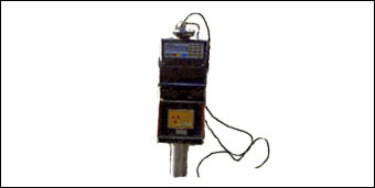
Working Principle
Fast neutrons are emitted from a decaying radioactive source (241Am/9Be) and when they collide with particles having the same mass as a neutron (i.e., protons, H+), they slow down dramatically, building a "cloud" of "thermalized" (slowed-down) neutrons. Since water is the main source of hydrogen in most soils, the density of slowed-down neutrons formed around the probe is nearly proportional to the volume fraction of water present in the soil.
Description
The probe configuration is in the form of a long and narrow cylinder, containing a source and detector. Measurements are made by introducing the probe into an access tube (previously installed into the soil). It is possible to determine soil moisture at different depths by hanging the probe in the tube at different depths. The soil moisture is obtained from the device based on a linear calibration between the count rate of slowed-down neutrons at the field (read from the probe), and the soil moisture content obtained from nearby field samples.
Advantages
- Robust and accurate (±0.005 ft3ft-3)
- Inexpensive per location (i.e., a large number of measurements can be made at different points with the same instrument)
- One probe allows for measuring at different soil depths
- Large soil sensing volume (sphere of influence with 4-16 in. radius, depending on moisture content)
- Not affected by salinity or air gaps
- Stable soil-specific calibration
Drawbacks
- Safety hazard, since it implies working with radiation. Even at 16 in. depth, radiation losses through soil surface have been detected
- Requires certified personnel
- Requires soil-specific calibration
- Heavy, cumbersome instrument
- Takes relative long time for each reading
- Readings close to the soil surface are difficult and not accurate
- Manual readings; cannot be automated due to hazard
- Expensive to buy
- The sphere of influence may vary according to the following reasons:
- 1. It increases as the soil dries, because the hydrogen concentration reduces, so that the probability of collision is smaller and thereby fast neutrons can travel further from the source.
- 2. It is smaller in fine texture soils, because they can hold more water, thus the probability of collision is higher.
- 3. If there are layers with large differences in water content due to changes in soil physical properties, the sphere of influence can have a distorted shape.
Time Domain Reflectometry
VR Instructions: To turn the sensor, click and drag your cursor around the movie window in any direction. Click the + and - buttons to zoom in and out. For problems viewing the VR, see VR Help.
Working Principle
The soil bulk dielectric constant (Ka b) is determined by measuring the time it takes for an electromagnetic pulse (wave) to propagate along a transmission line (TL) that is surrounded by the soil. Since the propagation velocity (v) is a function of Ka b, the latter is therefore proportional to the square of the transit time (t, in seconds) down and back along the TL:
Ka b = ( c/v ) 2 = (( c.t )/( 2.L )) 2 (2)>
where c is the velocity of electromagnetic waves in a vacuum (3.10 8 m/s or 186,282 mile/s) and L is the length of the TL embedded in the soil (in m or ft).
Description
A TDR instrument requires a device capable of producing a series of precisely timed electrical pulses with a wide range of high frequencies used by different devices (e.g., 0.02-3 GHz), which travel along a TL that is built with a coaxial cable and a probe. This high frequency provides a response less dependent on soil specific properties like texture, salinity or temperature.
The TDR probe usually consists of 2-3 parallel metal rods that are inserted into the soil acting as waveguides in a similar way as an antenna used for television reception. At the same time, the TDR instrument uses a device for measuring and digitizing the energy (voltage) level of the TL at intervals down to around 100 picoseconds. When the electromagnetic pulse traveling along the TL finds a discontinuity (i.e., probe-waveguides surrounded by soil) part of the pulse is reflected. This produces a change in the energy level of the TL. Thereby the travel time (t) is determined by analyzing the digitized energy levels.
Soil salinity or highly conductive heavy clay contents may affect TDR, since it contributes to attenuation of the reflected pulses. In other words, TDR is relatively insensitive to salinity as long as a useful pulse is reflected (i.e., as long as it can be analyzed). In soils with highly saline conditions, using epoxy-coated probe rods should solve the problem. However, this implies loss of sensitivity and change in calibration. It is interesting to notice that in addition to time of travel another characteristic of the pulse traveling through the soil (i.e., change in size or attenuation of the pulse) can be related to the soil electrical conductivity. Based on this some commercial devices incorporate the possibility of measuring water content and soil salinity simultaneously.
Advantages
- Accurate (±0.01 ft3ft-3)
- Soil specific-calibration is usually not required
- Easily expanded by multiplexing
- Wide variety of probe configurations
- Minimal soil disturbance
- Relatively insensitive to normal salinity levels
- Can provide simultaneous measurements of soil electrical conductivity
Drawbacks
- Relatively expensive equipment due to complex electronics
- Potentially limited applicability under highly saline conditions or in highly conductive heavy clay soils
- Soil-specific calibration required for soils having large amounts of bound water (i.e., those with high organic matter content, volcanic soils, etc.)
- Relatively small sensing volume (about 1.2 inch radius around length of waveguides)
Capacitance Probe
VR Instructions: To turn the sensor, click and drag your cursor around the movie window in any direction. Click the + and - buttons to zoom in and out. For problems viewing the VR, see VR Help.
Working Principle
The electrical capacitance of a capacitor that uses the soil as a dielectric depends on the soil water content. When connecting this capacitor (made of metal plates or rods imbedded in the soil) together with an oscillator to form an electrical circuit, changes in soil moisture can be detected by changes in the circuit operating frequency. This is the basis of the Frequency Domain (FD) technique used in Capacitance and Frequency Domain Reflectometry (FDR) sensors. In Capacitance sensors the dielectric permittivity of a medium is determined by measuring the charge time of a capacitor made with that medium. In FDR the oscillator frequency is swept under control within a certain frequency range to find the resonant frequency (at which the amplitude is greatest), which is a measure of water content in the soil.
Description
Probes usually consist of two or more electrodes (i.e., plates, rods, or metal rings around a cylinder) that are inserted into the soil. On the ring configuration the probe is introduced into a access tube installed in the field. Thus, when an electrical field is applied, the soil around the electrodes (or around the tube) forms the dielectric of the capacitor that completes the oscillating circuit. The use of an access tube allows for multiple sensors to take measurements at different depths.
A soil-specific calibration is recommended because the operating frequency of these devices is generally below 100 MHz. At these low frequencies the bulk permittivity of soil minerals may change and the estimation is more affected by temperature, salinity, bulk density and clay content.
Advantages
- Accurate after soil-specific calibration (±0.01 ft3ft-3)
- Can read in high salinity levels, where TDR fails
- Better resolution than TDR (avoids the noise that is implied in the waveform analysis performed by TDRs)
- Can be connected to conventional loggers (DC output signal)
- Flexibility in probe design (more than TDR)
- Some devices are relatively inexpensive compared to TDR due to use of low frequency standard circuitry
Drawbacks
- The sensing sphere of influence is relatively small (about 1.6 in.)
- For reliable measurements, it is extremely critical to have good contact between the sensor (or tube) and soil
- Careful installation is necessary to avoid air gaps
- Tends to have larger sensitivity to temperature, bulk density, clay content and air gaps than TDR
- Needs soil-specific calibration
Combined Probe
VR Instructions: To turn the sensor, click and drag your cursor around the movie window in any direction. Click the + and - buttons to zoom in and out. For problems viewing the VR, see VR Help.
Working Principle
The electrical capacitance of a capacitor that uses the soil as a dielectric depends on the soil water content. When connecting this capacitor (made of metal plates or rods imbedded in the soil) together with an oscillator to form an electrical circuit, changes in soil moisture can be detected by changes in the circuit operating frequency. This is the basis of the Frequency Domain (FD) technique used in Capacitance and Frequency Domain Reflectometry (FDR) sensors. In Capacitance sensors the dielectric permittivity of a medium is determined by measuring the charge time of a capacitor made with that medium. In FDR the oscillator frequency is swept under control within a certain frequency range to find the resonant frequency (at which the amplitude is greatest), which is a measure of water content in the soil.
Description
Probes usually consist of two or more electrodes (i.e., plates, rods, or metal rings around a cylinder) that are inserted into the soil. On the ring configuration the probe is introduced into a access tube installed in the field. Thus, when an electrical field is applied, the soil around the electrodes (or around the tube) forms the dielectric of the capacitor that completes the oscillating circuit. The use of an access tube allows for multiple sensors to take measurements at different depths.
A soil-specific calibration is recommended because the operating frequency of these devices is generally below 100 MHz. At these low frequencies the bulk permittivity of soil minerals may change and the estimation is more affected by temperature, salinity, bulk density and clay content.
Advantages
- Accurate after soil-specific calibration (±0.01 ft3ft-3)
- Can read in high salinity levels, where TDR fails
- Better resolution than TDR (avoids the noise that is implied in the waveform analysis performed by TDRs)
- Can be connected to conventional loggers (DC output signal)
- Flexibility in probe design (more than TDR)
- Some devices are relatively inexpensive compared to TDR due to use of low frequency standard circuitry
Drawbacks
- The sensing sphere of influence is relatively small (about 1.6 in.)
- For reliable measurements, it is extremely critical to have good contact between the sensor (or tube) and soil
- Careful installation is necessary to avoid air gaps
- Tends to have larger sensitivity to temperature, bulk density, clay content and air gaps than TDR
- Needs soil-specific calibration
Frequency Domain Reflectometry (FDR)
Working Principle
The electrical capacitance of a capacitor that uses the soil as a dielectric depends on the soil water content. When connecting this capacitor (made of metal plates or rods imbedded in the soil) together with an oscillator to form an electrical circuit, changes in soil moisture can be detected by changes in the circuit operating frequency. This is the basis of the Frequency Domain (FD) technique used in Capacitance and Frequency Domain Reflectometry (FDR) sensors. In Capacitance sensors the dielectric permittivity of a medium is determined by measuring the charge time of a capacitor made with that medium. In FDR the oscillator frequency is swept under control within a certain frequency range to find the resonant frequency (at which the amplitude is greatest), which is a measure of water content in the soil.
Description
Probes usually consist of two or more electrodes (i.e., plates, rods, or metal rings around a cylinder) that are inserted into the soil. On the ring configuration the probe is introduced into a access tube installed in the field. Thus, when an electrical field is applied, the soil around the electrodes (or around the tube) forms the dielectric of the capacitor that completes the oscillating circuit. The use of an access tube allows for multiple sensors to take measurements at different depths.
Advantages
- Accurate after soil-specific calibration (±0.01 ft3ft-3)
- Can read in high salinity levels, where TDR fails
- Better resolution than TDR (avoids the noise that is implied in the waveform analysis performed by TDRs)
- Can be connected to conventional loggers (DC output signal)
- Flexibility in probe design (more than TDR)
- Some devices are relatively inexpensive compared to TDR due to use of low frequency standard circuitry
Drawbacks
- The sensing sphere of influence is relatively small (about 1.6 in.)
- For reliable measurements, it is extremely critical to have good contact between the sensor (or tube) and soil
- Careful installation is necessary to avoid air gaps
- Tends to have larger sensitivity to temperature, bulk density, clay content and air gaps than TDR
- Needs soil-specific calibration
Amplitude Domain Reflectometry
VR Instructions: To turn the sensor, click and drag your cursor around the movie window in any direction. Click the + and - buttons to zoom in and out. For problems viewing the VR, see VR Help.
Working Principle
When an electromagnetic wave (energy) traveling along a transmission line (TL) reaches a section with different impedance (which has two components: electrical conductivity and dielectric constant), part of the energy transmitted is reflected back into the transmitter. The reflected wave interacts with the incident wave producing a voltage standing wave along the TL, i.e., change of wave amplitude along the length of the TL. If the soil/probe combination is the cause for the impedance change in the TL, measuring the amplitude difference will give the impedance of the probe (Gaskin and Miller, 1996; Nakashima et al., 1998). The influence of the soil electrical conductivity is minimized by choosing a signal frequency, so that the soil water content can be estimated from the soil/probe impedance.
Description
Impedance sensors use an oscillator to generate a sinusoidal signal (electromagnetic wave at a fixed frequency, e.g., 100 MHz) that is applied to a coaxial TL that extends into the soil through an array of parallel metal rods, the outer of which forms an electrical shield around the central signal rod. This rod arrangement acts as an additional section of the TL, having impedance that depends on the dielectric constant of the soil between the rods.
Advantages
- Accurate with soil-specific calibration (±0.01 ft3ft-3; ±0.05 ft3ft-3 without it)
- Allows measurements in highly saline conditions (up to 20 dS/m)
- Minimal soil disturbance
- Can be connected to conventional loggers (DC output signal)
- Inexpensive due to standard circuitry
- Not affected by temperature
- In situ estimation of soil bulk density possible (Wijaya et al., 2002)
Drawbacks
- Soil-specific calibration recommended for reliable measurements
- Measurement affected by air gaps, stones or channeling water directly onto the probe rods
- Small sensing volume (0.27 in3)
Phase Transmission
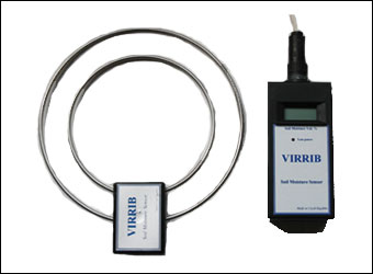
Working Principle
After having traveled a fixed distance, a sinusoidal wave will show a phase shift relative to the phase at the origin. This phase shift depends on the length of travel along the TL, the frequency and the velocity of propagation. Since velocity of propagation is related to soil moisture content, for a fixed frequency and length of travel soil water content can be determined by this phase shift.
Description
The probe uses a particular waveguide design (two open concentric metal rings), so that phase measuring electronics can be applied at the beginning and ending of the waveguides.
Advantages
- Accurate with soil-specific calibration (±0.01 ft3ft-3)
- Large sensing soil volume (4-5 gallons)
- Can be connected to conventional loggers (DC output signal)
- Inexpensive
Drawbacks
- Significant soil disturbance during installation due to concentric rings sensor configuration
- Requires soil-specific calibration
- Sensitive to salinity levels >3 dS/m
- Reduced precision, because the generated pulse gets distorted during transmission
- Needs to be permanently installed in the field
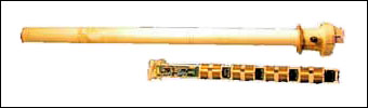
Time Domain Transmission
VR Instructions: To turn the sensor, click and drag your cursor around the movie window in any direction. Click the + and - buttons to zoom in and out. For problems viewing the VR, see VR Help.
Working Principle
This method measures the one-way time for an electromagnetic pulse to propagate along a transmission line (TL). Thus, it is similar to TDR, but requires an electrical connection at the beginning and ending of the TL. Notwithstanding, the circuit is simple compared with TDR instruments.
Description
The probe has a waveguide design (bent metal rods), so that the beginning and ending of the transmission line are inserted into the electronic block. Alternatively, the sensor consists of a long band (~3 ft), having an electronic block at both ends.
Advantages
- Accurate (±0.01-0.02 ft3ft-3)
- Large sensing soil volume (0.2-1.6 gallons)
- Can be connected to conventional loggers (DC output signal)
- Inexpensive due to standard circuitry
Drawbacks
- Reduced precision, because the generated pulse is distorted during transmission
- Soil disturbance during installation
- Needs to be permanently installed in the field
-
-
Tensiometric Measurement
-
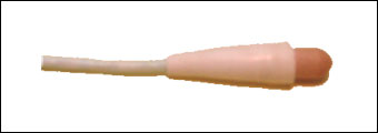
Tensiometer
VR Instructions: To turn the sensor, click and drag your cursor around the movie window in any direction. Click the + and - buttons to zoom in and out. For problems viewing the VR, see VR Help.
Working Principle
When a sealed water-filled tube is placed in contact with the soil through a permeable and saturated porous material, water (inside the tube) comes into equilibrium with the soil solution (i.e., it is at the same pressure potential as the water held in the soil matrix). Hence, the soil water matric potential is equivalent to the vacuum or suction created inside the tube.
Description
The tensiometer consists of a sealed water-filled plastic tube with a ceramic cup at one end and a negative pressure gauge (vacuometer) at the other. The shape and size of the ceramic cup can be variable and the accuracy depends on the gauge or transducer used (about 0.01 bar). Typically the measurement range is 0-0.80 bar, although there are low-tension versions (0-0.40 bar) designed for coarse soils.
Advantages
- Direct reading
- Up to 4 inch measurement sphere radius
- Continuous reading possible when using pressure transducer
- Electronics and power consumption avoidable
- Well-suited for high frequency sampling or irrigation schedules
- Minimal skill required for maintenance
- Not affected by soil salinity, because salts can move freely in and out across the porous ceramic cup
- Inexpensive
Drawbacks
- Limited soil suction range (<1 bar)
- Relatively slow response time
- Requires intimate contact with soil around the ceramic cup for consistent readings and to avoid frequent discharge (breaking of water column inside)
- Especially in swelling or coarse soils, the ceramic cup can loose contact with soil, thus requiring reinstallation
- Requires frequent maintenance (refilling) to keep the tube full of water, specially in hot dry weather
Gypsum Block
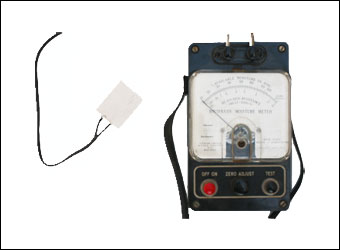
Working Principle
The electrical resistance between electrodes embedded in a porous medium (block) is proportional to its water content, which is related to the soil water matric potential of the surrounding soil. Electrical resistance reduces as the soil, hence the block, dries.
Description
A gypsum block sensor constitutes an electrochemical cell with a saturated solution of calcium sulfate as electrolyte. The resistance between the block-embedded electrodes is determined by applying a small AC voltage (to prevent block polarization) using a Wheatstone bridge. Since changes to the soil electrical conductivity would affect readings, gypsum is used as a buffer against soil salinity changes (up to a certain level). The inherent problem is that the block dissolves and degrades over time (especially in saline soils) losing its calibration properties. It is recommended that the block pore size distribution match the soil texture being used. The readings are temperature dependent (up to 3% change/°C) and field measured resistance should be corrected for differences between calibration and field temperatures. Some reading devices contain manual or self-compensating features for temperature or the manufacture provides correction charts or equations. Measurement range is 0.3-2.0 bar.
Advantages
- Up to 4 inch measurement cylinder radius
- No maintenance needed
- Simple and inexpensive
- Salinity effects buffered up to 6 dS/m
- Well suited for irrigation where only "full" and "refill" points are required
- Suited to regulated-deficit irrigation
Drawbacks
- Low resolution, limited use in research
- Block cannot be used for measurements around saturation (0-0.3 bar)
- Block properties change with time, because of clay deposition and gypsum dissolution. Degradation speed depends on soil type, amount of >rainfall and irrigation, and also the type of gypsum block used
- Very slow reaction time. It does not work well in sandy soils, where water drains more quickly than the instrument can equilibrate
- Not suitable for swelling soils
- Inaccurate readings due to the block hysteresis (i.e., at a fixed soil water potential, the sensor can display different resistance when wetting than when drying)
- Temperature dependent. If connected to a logging system, another variable and sensor for temperature must be added to the system
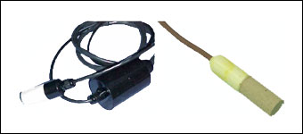
Granular Matrix Sensors (GMS)
VR Instructions: To turn the sensor, click and drag your cursor around the movie window in any direction. Click the + and - buttons to zoom in and out. For problems viewing the VR, see VR Help.
Working Principle
The electrical resistance between electrodes embedded in a porous medium (block) is proportional to its water content, which is related to the soil water matric potential of the surrounding soil. Electrical resistance reduces as the soil, hence the block, dries.
Description
The sensor consists of electrodes embedded in a granular quartz material, surrounded by a synthetic membrane and a protective stainless steel mesh. Inside, gypsum is used to buffer against salinity effects. This kind of porous medium allows for measuring in wetter soil conditions and lasts longer than the gypsum blocks. However, even with good sensor-soil contact, GMS have re-wetting problems after they have been dried to very dry levels. This is because of the reduced ability of water films to re-enter the coarse medium of the GMS from a fine soil. The GMS material allows for measurements closer to saturation. Measurement range is 0.10-2.0 bar.
Advantages
- Reduces the problems inherent to gypsum blocks (i.e., loss of contact with the soil by dissolving, and inconsistent pore size distribution)
- Up to 4 inch measurement cylinder radius
- No maintenance needed
- Simple and inexpensive
- Salinity effects buffered up to 6 dS/m
- Suited to regulated-deficit irrigation
Drawbacks
- Low resolution, limited use in research
- Slow reaction time. It does not work well in sandy soils, where water drains more quickly than the instrument can equilibrate
- Not suitable for swelling soils
- If the soil becomes too dry, the sensor must be pulled out, re-saturated and installed again
- Temperature dependence. If connected to a logging system, another variable and sensor for temperature must be added to the system
Heat Dissipation
Working Principle
The thermal conductivity of water produces heat dissipation, so that a dry material will heat up faster than a wet one. In other words, the heat flow in a porous material is proportional to its water content.
Description
A thermal heat probe consists of a porous block containing a heat source and an accurate temperature sensor. The block temperature is measured before and after the heater is powered for a few seconds. Thereby, block moisture is obtained from the temperature variation. Since the porous block, placed in contact with the soil, is equilibrated with the soil water, its characteristic curve will give the soil water potential. Hence, the sensor must be provided with the calibrated relationship between the measured change in temperature and soil water potential. Measurement range: 0.1-30 bar (less accurate for 10-30 bar range).
Advantages
- Wide measurement range
- No maintenance required
- Continuous reading possible
- Not affected by salinity because measurements are based on thermal conductivity
Drawbacks
- Needs a sophisticated controller/logger to control heating and measurement operations
- Slow reaction time. It does not work well in sandy soils, where water drains more quickly than the instrument can equilibrate
- Fairly large power consumption for frequent readings
Soil Psychrometer
Working Principle
Under vapor equilibrium conditions, water potential of a porous material is directly related to the vapor pressure of the air surrounding the porous medium. This means that the soil water potential is determined by measuring the RH of a chamber inside a porous cup equilibrated with the soil solution (Campbell and Gardner, 1971).
Description
A soil psychrometer consists of a ceramic shield or screen building an air chamber, where a thermocouple is located. The screen type is recommended for high salinity environments. RH in the air chamber is calculated from the "wet bulb" vs "dry bulb" temperature difference. Measurement range: 0.5-30 bar (less accurate for 10-30 bar range).
Advantages
- High sensitivity
- Scientifically rigorous readings (except in wetter soil conditions)
- Suitable where typical moisture conditions are very dry
Drawbacks
- Not recommended at shallow soil depths, due to high susceptibility to thermal gradient
- Small sensing volume
- Very slow reaction time, because reaching vapor equilibrium takes time
- Low accuracy in the wet range
- Specialized equipment is required for the sensor's excitation and reading
-